Beste,
zoals velen weten zijn de stuurwielen van de clioRS ( voor zover ik weet )
niet van super goedde qualiteit ! nu is mijn linker grip er half af, maar een nieuw stuur van 350 euro vind ik geen porum !
nu heb ik ergens gezien dat een clio 3 rs stuur ook in een clio 2 rs past ?
kan iemand dit beamen ? werkt de airbag dan ook gewoon ? is de cruzecontrol gewoon bedienbaar via de aansluiting waar een clio2ph3 stuur ook mee aangestuurt word ??
alvast bedankt voor de info !
Thijn
clio 3 rs stuur in een clio 2 rs.
-
Adrian
- Berichten: 1383
- Lid geworden op: wo 25 apr 2007 11:37
- Car: Clio V6, 5 AlpineT
- Locatie: Brouwershaven
- Contacteer:
Clio V6 -- 5 Alpine Turbo -- Clio II RS -- 4CV Grand Luxe -- 5 TR -- Clio II Ragnotti dCi "daily" -- Megané III estate dCi
-- ClioV6register.nl--
-- ClioV6register.nl--
kan de website niet openen. moet je je voor aanmelden !
is de cliov6 qua stuur naaf enzo hetzelfde als de clio2ph2?
alvast bedankt.
is de cliov6 qua stuur naaf enzo hetzelfde als de clio2ph2?
alvast bedankt.
-
Adrian
- Berichten: 1383
- Lid geworden op: wo 25 apr 2007 11:37
- Car: Clio V6, 5 AlpineT
- Locatie: Brouwershaven
- Contacteer:
Dat zag ik ook. Was al voor je bezig. Duurt heel even..  V6 stuur is hetzelfde
Er komt zo ff een artikeltje
Er komt zo ff een artikeltje
Clio V6 -- 5 Alpine Turbo -- Clio II RS -- 4CV Grand Luxe -- 5 TR -- Clio II Ragnotti dCi "daily" -- Megané III estate dCi
-- ClioV6register.nl--
-- ClioV6register.nl--
toppertje ! had me al snel aangemeld, maar moet wachten tot de administrator me accepteerd !

-
Adrian
- Berichten: 1383
- Lid geworden op: wo 25 apr 2007 11:37
- Car: Clio V6, 5 AlpineT
- Locatie: Brouwershaven
- Contacteer:
Bij deze
[quote="V6Clio.net"][/quote]
Fit a Clio 197/200 Steering Wheel To A V6 255
Thanks to benkay for this article.
Topic date: 08/08/2011
Topic link
Updated 18/01/2012 : Added washer details
Why?
Well, as most of you will no doubt have noticed, the standard fit Renault wheel on the 172 Ph2/182 and V6 255 is atrocious quality. You may notice the material around the rim of your wheel graining/melting and the rubberised thumbgrips will begin to wear and eventually crack. As an example of just how poor they are, my wheel has only done 16,000 miles and was already feeling sticky and starting to melt!!! Typical Renault!
Anyway, this is for people wanting to retain the OEM look, keep the airbag and have the cruise control capabilities. Cheaper, and certainly easier, options are avaiable but in my mind this is the best! Now I've done it, I wish I'd done it earlier. It transforms the feel of the car, and despite being essentially the same diameter, it feels much smaller because it's so much more chunky. A real worthy upgrade, if you're unsure go for it! You won't be disappointed....
The Tools For The Job
- Large-ish flat bladed screwdriver (for levering)
- 8mm spanner
- Torx 50 bit
- Ratchet
- Extension bar
- Loctite (blue or red)
- Side-cutters
- Wire strippers (not essential)
- Soldering iron
- Solder
- Heatshrink wrap
- Small paperclip or small electrical screwdriver
- Stanley knife / scalpel
- Thin plastic material or large metal washer (more details below)
- New wheel with new airbag!! (RPD Link)
Guide
1. DISCONNECT THE BATTERY!!!!! We don't want the airbag making a Picasso painting of your face when you start fiddling with it. I'm sure most people attempting this would know, but the battery is under the bonnet tray. Disconnect the negative terminal of the battery, you will need the 8mm spanner to undo the clamp. Now leave for 30 minutes to allow any residual charge to dissipate.
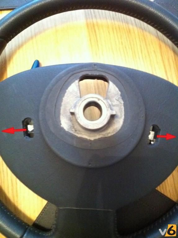
2. Time to get stuck in. First task is to remove the airbag. Put the key in the ignition and turn to first click. This will disengage the steering lock. First rotate the wheel 90 degrees to the right. Feel around the back at what is now the 12 o'clock position, and you will find a slot and a metal retainer. Using a flat bladed screwdriver or similar, you need to hook the metal sprung retainers over the tabs to loosen the airbag module. Work one side off first, pushing in the horn helps to relieve some of the pressure, but it can still be a pig. Once one side is done, rotate the wheel so it points 90 degrees to the left and repeat. Once both are unclipped, return wheel to straight ahead position. Below a picture of the wheel showing the lugs you need to hook the retainers off of :
[img]http://i188.photobucket.com/albums/z183 ... 24ac03.jpg[/img]
3. Now the airbag is loose, pull it towards you until it unclips from all its various fixings. You will see it is connected on each side (left and right). To undo these connectors, lift up the locking part (there's a little tab you can use to lever it up). Once this bit is unlocked, now the whole plug pulls out of the airbag, just wobble it side to side a bit and they eventually come off. Didn't get a great photo of this, but below shows the disconnecter terminals, so you can see how they work.
[img]http://i188.photobucket.com/albums/z183 ... ac6580.jpg[/img]
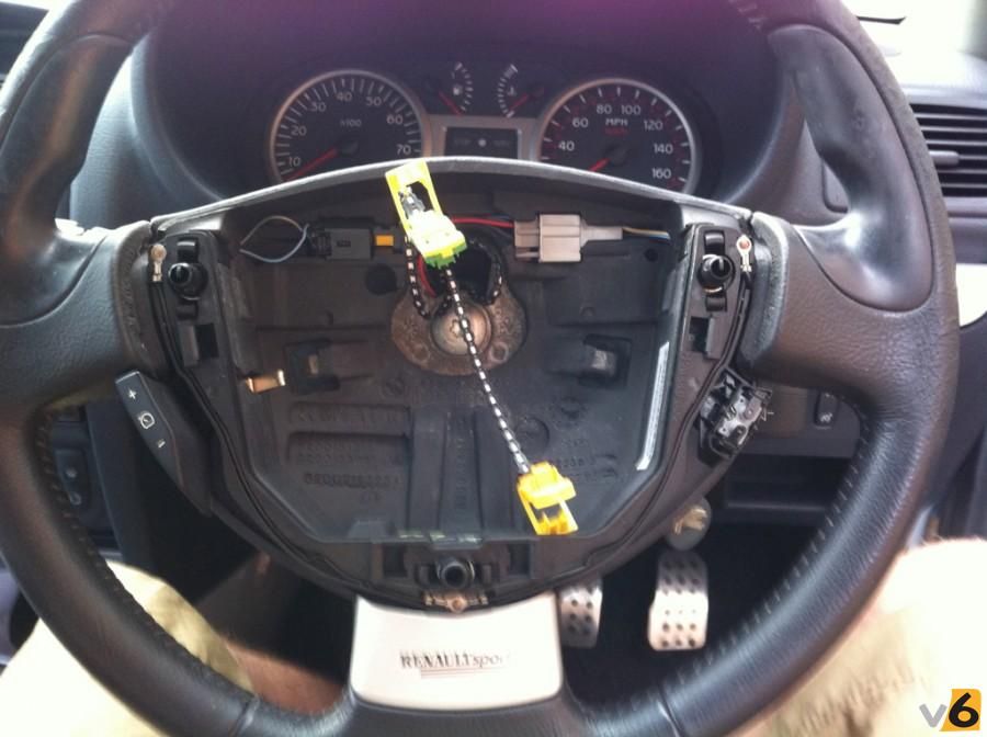
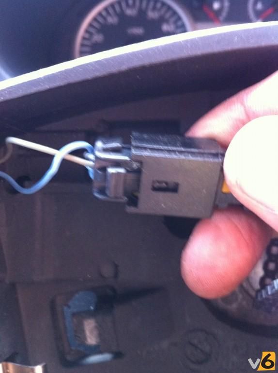
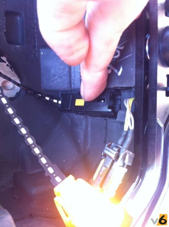
4. Right, now you're looking at a bare wheel with various connectors etc. around the place. First, let's disconnect the cruise control connector. This is the one in the top left of the wheel. Fairly simple, push the obvious "button"....
[img]http://i188.photobucket.com/albums/z183 ... 6e2776.jpg[/img]
...and simultaneously pull apart, thus :-
[img]http://i188.photobucket.com/albums/z183 ... f7e285.jpg[/img]
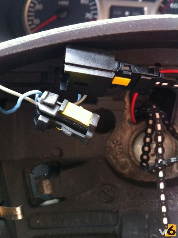
5. Next up, the horn(s). This is the grey connector in the top right of the wheel. :
[img]http://i188.photobucket.com/albums/z183 ... 9674d0.jpg[/img]
Just squeeze the lever....
[img]http://i188.photobucket.com/albums/z183 ... ed0db6.jpg[/img]
...and pull!! (You'll be getting good by now)
[img]http://i188.photobucket.com/albums/z183 ... 778a34.jpg[/img]
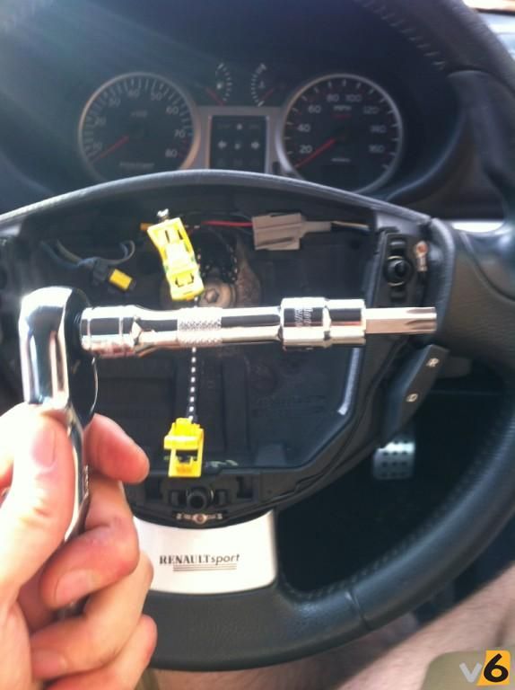
6. Right, time to get that pesky wheel off....it's held on by just one bolt. This one...surprisingly...
[img]http://i188.photobucket.com/albums/z183 ... 6225ba.jpg[/img]
For this, you'll need your ratchet, an extension bar to clear the wheel recess and a Torx/Star Size 50 bit.
[img]http://i188.photobucket.com/albums/z183 ... 16469d.jpg[/img]
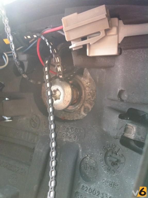
Undo the bolt, but not all the way!!! You'll need to hold the wheel rim to stop the wheel trying to rotate. Leave the bolt with a few threads remaining engaged...like so :
[img]http://i188.photobucket.com/albums/z183 ... 400b50.jpg[/img]
7. Now go all Hulk Hogan on the wheel. Give it a few taps towards you with your hand around the circumference, wobble it side to side, pull on it, use the Force, whatever, until the wheel pops off and pulls forward until it is stopped by the bolt...you did leave the bolt in slightly didn't you?? As you will now realise, without leaving the bolt in, when the wheel released suddenly you would probably have ripped off all the wires from the column too. Good trick eh?
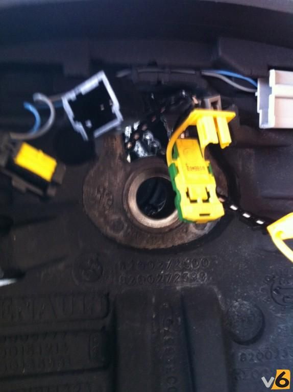
8. Go ahead and undo the bolt completely, keep it somewhere safe! You'll be left with this...
[img]http://i188.photobucket.com/albums/z183 ... 5136d2.jpg[/img]
So, pull the wheel towards you off the spline and feed all the wires carefully out through the hole in the back of the wheel.
9. Now comes the first tricky part. As you may notice, the cruise control connectors are different on the 197 wheel vs. the standard wheel. There's many ways to do this, I was adamant that I didn't want to cut any of the car's loom, so that's the method shown here.
First up, snip off the connector from the old wheel. Cut it so you leave about 1cm of the wires sticking out of it. This'll leave you with a wheel looking like this...
[img]http://i188.photobucket.com/albums/z183 ... ae4d04.jpg[/img]
You can now throw it in the bin, the best place for it
10. OK, now snip the cruise control connector off your 197 wheel. Snip the wires as close to the connector as you can. You can throw this little connector away, it's not needed again.
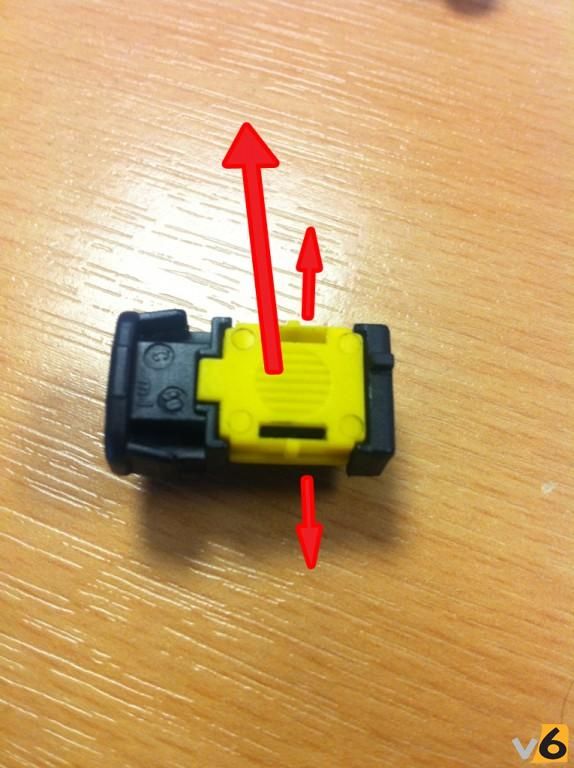
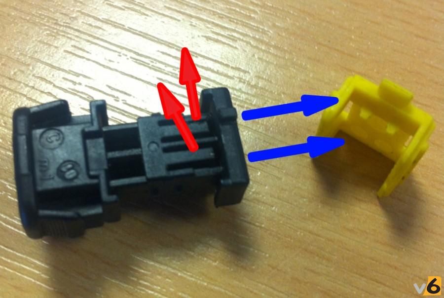
11. Now remove the pins from the original connector. These photos show the pins already removed, sorry about that! To remove the pins, pop off the yellow cap as below (pull wings out sideways and then lift it up)...
[img]http://i188.photobucket.com/albums/z183 ... 9b0e59.jpg[/img]
Now lift the little plastic tabs one at a time, carefully, you don't want to snap them. As they are raised (red arrows), pull the pins out one by one in the direction of the blue arrows. You should have that cm of wire sticking out the end to pull on.
[img]http://i188.photobucket.com/albums/z183 ... 88eb5e.jpg[/img]
13. OK, soldering time!!! First get prepared.
Let's start with the 2 connector pins you just removed.
- You'll have two wires about 1cm long each coming out of the pin
- Strip as much insulation as you can off of the two wires
- Now twist all the exposed copper strands together
- Use some solder to "tin" the copper strands.
- Repeat this procedure for both pins.
Now, the steering wheel wires.
- You have 2 cut grey wires and 2 cut yellowy-green wires
- Strip about 8mm of insulation off all the wires
- Find the 2 grey wires and twist all their copper strands together. Now tin the merged wires with some solder
- Find the 2 yellowy-green wires. Again, twist all their copper strands together and tin with some solder
- Cut 2 lengths of heatshrink. About 2 cm should do it. Slide one over the combined grey wires and push it up and out of the way for now. Slide the other wrap over the combined yellowy-green wires.
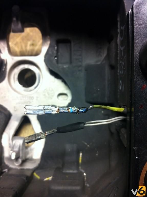
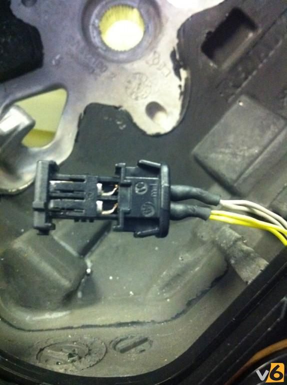
Right, you're prepared. now you need to solder a pin onto each set of wires. Try and make the soldered joint as streamlined and neat as possible!! So, one pin onto the grey wires and one pin onto the yellowy-green wires. Here's mine, mid progress...
[img]http://i188.photobucket.com/albums/z183 ... 3818d7.jpg[/img]
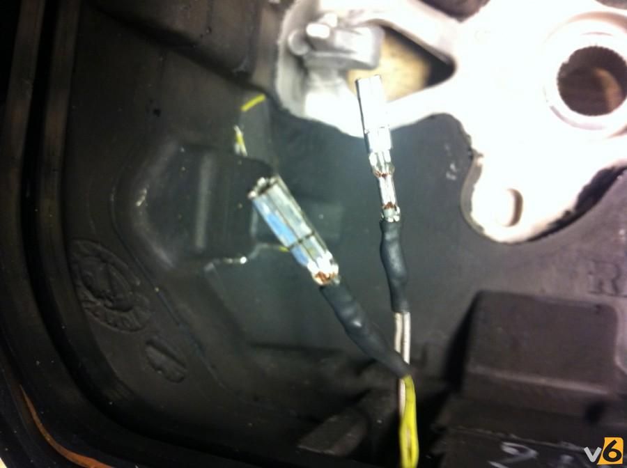
Once you're happy the solder is good, pull the heatshrink down the wires and over the joint. Heat with a heat-gun to create a nice neat joint. Here are mine...
[img]http://i188.photobucket.com/albums/z183 ... f7999e.jpg[/img]
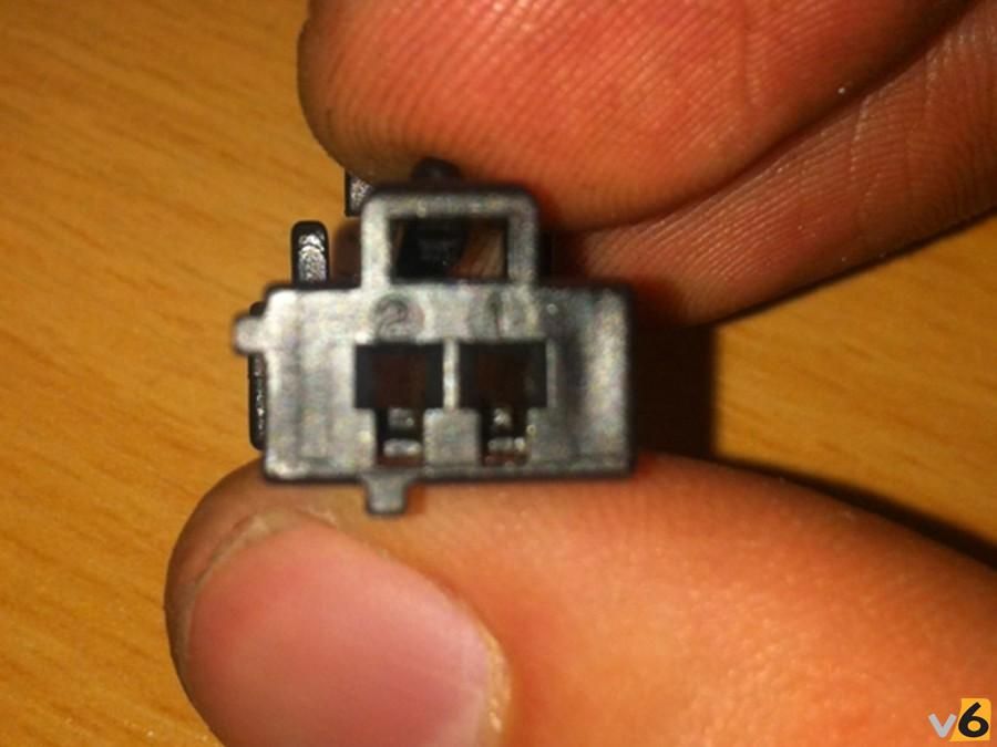
14. Now, let's get the connector block back on. First thing first, look on the end of the connector....
[img]http://i188.photobucket.com/albums/z183 ... 4132be.jpg[/img]
See that "1" and "2" ???? The grey wires' pin needs to go into the "1" position, and the yellowy-green wires' pin needs to go into the "2" position!!!
The pins will only go in the "right way up" as the hole is rectangular. It's just a cast of push the pins in the same way they were removed. No need to lift the tabs this time, they'll click in and lock the pins in place, like so...
[img]http://i188.photobucket.com/albums/z183 ... a58cf4.jpg[/img]
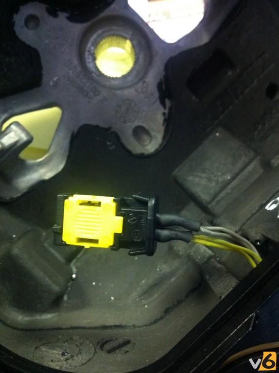
Now just snap on the yellow cover...
[img]http://i188.photobucket.com/albums/z183 ... 933980.jpg[/img]
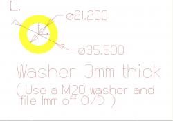
15. RIght, that's the electronicery out of the way, onto the mechanical headache....
So, if you hold the original wheel up against the 197 wheel, you'll notice the spline is longer on the 197 wheel and the rear of the wheel is a different side profile too. If you just bolt the 197 wheel on without any modification it rubs on the plastic column cowlings, adding friction to the steering, sounding awful and stopping the wheel self-centreing.
You need to find a standard M20 metal washer and reduce the outer diameter slightly. I used a linishing machine, but you could also simply use a file to achieve the same result. Thanks to Russo for producing this drawing of exactly what you need to achieve :
[img]http://i188.photobucket.com/albums/z183 ... 0131cd.jpg[/img]
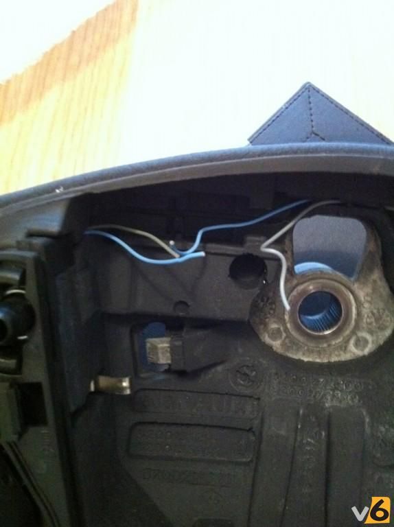
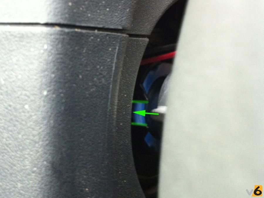
16. OK, nearly there. So thread your modified washer onto the steering spline. Now offer up the 197 steering wheel. Feed all the various wires (2 airbags, horn and cruise control) through the hole in the wheel. Make sure the horn wires are sat in their little retainer as they tend to work their way out. Line up the wheel with the spline (there is a master spline, so the wheel can only go on in one orientation). Push the wheel on slowly. Make sure that the two lugs on the steering wheel will go into the two plastic forks on the indicator self-cancelling mechanism. See below (bits to watch out for highlighted in green):
[img]http://i188.photobucket.com/albums/z183 ... 0bee68.jpg[/img]
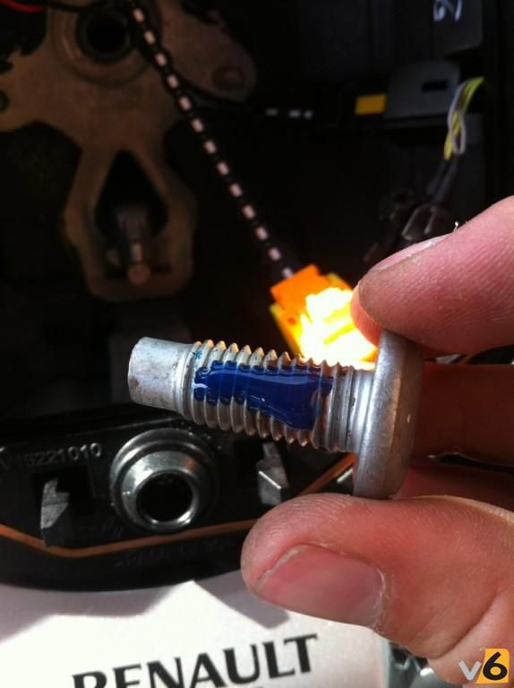
17. Alright, we're tanking now, easy sailing from now on. Well, almost. Go ahead and bolt the wheel on. USE THREADLOCK!!!!!!! (that mistake's been made once, LINK)
[img]http://i188.photobucket.com/albums/z183 ... b9dcc8.jpg[/img]
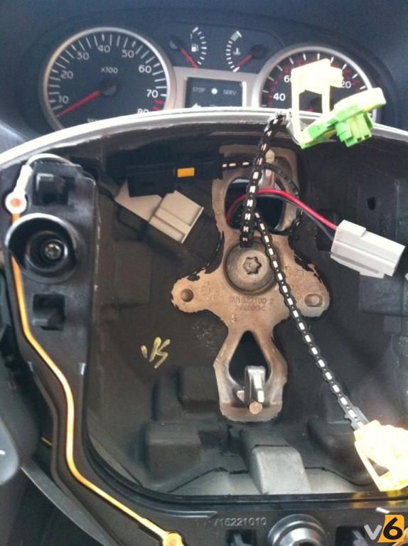
18. Torque the bolt pretty tight, the wheel shouldn't be able to move in our out, side to side nor up and down! You should now be looking at something like this...
[img]http://i188.photobucket.com/albums/z183 ... 33c3f9.jpg[/img]
19. Go ahead and connect the horn up. Again make sure the wires are sat in their little retaining groove behind the wheel.
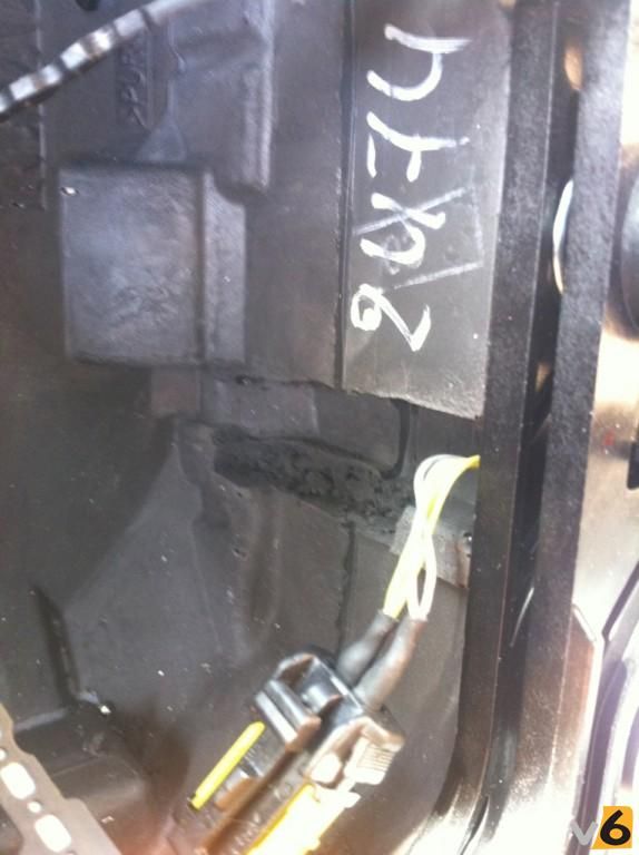
20. RIght, next problem. The bigger connector from the original wheel hasn't got room to sit in the new wheel. We need to open up the rubber channel down the right hand side of the wheel. Just use a stanley knife or scalpel and cut out the rubber, it's quite soft. Be careful not to stick the knife straight through the back of the wheel, this IS possible, I learnt the hard way [/b}. OK, your groove should end up something like this..
[img]http://i188.photobucket.com/albums/z183 ... 84fc82.jpg[/img]
As you can see, the connector can now fit much more "flush" than previously....
[img]http://i188.photobucket.com/albums/z183 ... 71ad7f.jpg[/img]
21. Go ahead and connect up both halves of the cruise control system. Push the connector into your new groove so it's out of the way.
22. You'll notice you have 1 green airbag connector and 1 orange airbag connector. The green one is OK, but the orange one needs modification to fit the new airbag. The little square tab marked with arrows below needs to be removed. You can again use a craft knife or similar, the plastic is quite easy to cut.
[img]http://i188.photobucket.com/albums/z183 ... f977a7.jpg[/img]
23. Right then, on the 197 airbag you'll notice the right hand socket is green. No prizes for guessing the green connector goes in here. Go ahead and push the connector into place and then close the locking tab firmly. Keep holding the weight of the airbag so not too much strain is put on the green connector and push the modified orange connector into place on the left side of the 197 airbag (the plug on the airbag is actually marked purple).
24. You now have the wheel all connected up. Take a quick glance behind the airbag and make sure all the wires are recessed as well as possible (especially the CC wires). The airbag simply pushes into place. There's two metal tabs at the back and two plastic retaning tabs on each side at the front. Just make sure the airbag is square up to the wheel and push all over, quite firmly. You should hear (and see) everything clip into place.
25. Re-attach negative terminal to the battery. Make sure it's tight. Re-assemble the bonnet area (not forgetting the rubber weather seal!!)
25. Ta-daaaa! You're done. Take her for a spin, check the horn works, the cruise control functions as expected and crash into a wall to check the airbag will deploy.
[img]http://i188.photobucket.com/albums/z183 ... f87712.jpg[/img]
[quote="V6Clio.net"][/quote]
Fit a Clio 197/200 Steering Wheel To A V6 255
Thanks to benkay for this article.
Topic date: 08/08/2011
Topic link
Updated 18/01/2012 : Added washer details
Why?
Well, as most of you will no doubt have noticed, the standard fit Renault wheel on the 172 Ph2/182 and V6 255 is atrocious quality. You may notice the material around the rim of your wheel graining/melting and the rubberised thumbgrips will begin to wear and eventually crack. As an example of just how poor they are, my wheel has only done 16,000 miles and was already feeling sticky and starting to melt!!! Typical Renault!
Anyway, this is for people wanting to retain the OEM look, keep the airbag and have the cruise control capabilities. Cheaper, and certainly easier, options are avaiable but in my mind this is the best! Now I've done it, I wish I'd done it earlier. It transforms the feel of the car, and despite being essentially the same diameter, it feels much smaller because it's so much more chunky. A real worthy upgrade, if you're unsure go for it! You won't be disappointed....
The Tools For The Job
- Large-ish flat bladed screwdriver (for levering)
- 8mm spanner
- Torx 50 bit
- Ratchet
- Extension bar
- Loctite (blue or red)
- Side-cutters
- Wire strippers (not essential)
- Soldering iron
- Solder
- Heatshrink wrap
- Small paperclip or small electrical screwdriver
- Stanley knife / scalpel
- Thin plastic material or large metal washer (more details below)
- New wheel with new airbag!! (RPD Link)
Guide
1. DISCONNECT THE BATTERY!!!!! We don't want the airbag making a Picasso painting of your face when you start fiddling with it. I'm sure most people attempting this would know, but the battery is under the bonnet tray. Disconnect the negative terminal of the battery, you will need the 8mm spanner to undo the clamp. Now leave for 30 minutes to allow any residual charge to dissipate.
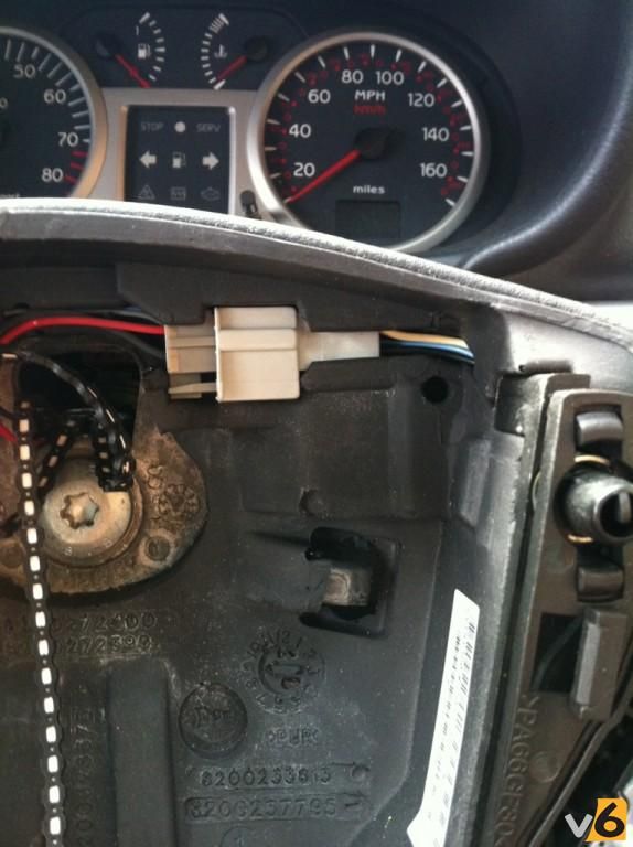
2. Time to get stuck in. First task is to remove the airbag. Put the key in the ignition and turn to first click. This will disengage the steering lock. First rotate the wheel 90 degrees to the right. Feel around the back at what is now the 12 o'clock position, and you will find a slot and a metal retainer. Using a flat bladed screwdriver or similar, you need to hook the metal sprung retainers over the tabs to loosen the airbag module. Work one side off first, pushing in the horn helps to relieve some of the pressure, but it can still be a pig. Once one side is done, rotate the wheel so it points 90 degrees to the left and repeat. Once both are unclipped, return wheel to straight ahead position. Below a picture of the wheel showing the lugs you need to hook the retainers off of :
[img]http://i188.photobucket.com/albums/z183 ... 24ac03.jpg[/img]
3. Now the airbag is loose, pull it towards you until it unclips from all its various fixings. You will see it is connected on each side (left and right). To undo these connectors, lift up the locking part (there's a little tab you can use to lever it up). Once this bit is unlocked, now the whole plug pulls out of the airbag, just wobble it side to side a bit and they eventually come off. Didn't get a great photo of this, but below shows the disconnecter terminals, so you can see how they work.
[img]http://i188.photobucket.com/albums/z183 ... ac6580.jpg[/img]
4. Right, now you're looking at a bare wheel with various connectors etc. around the place. First, let's disconnect the cruise control connector. This is the one in the top left of the wheel. Fairly simple, push the obvious "button"....
[img]http://i188.photobucket.com/albums/z183 ... 6e2776.jpg[/img]
...and simultaneously pull apart, thus :-
[img]http://i188.photobucket.com/albums/z183 ... f7e285.jpg[/img]
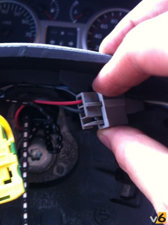
5. Next up, the horn(s). This is the grey connector in the top right of the wheel. :
[img]http://i188.photobucket.com/albums/z183 ... 9674d0.jpg[/img]
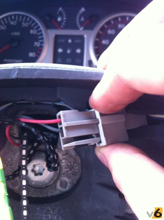
Just squeeze the lever....
[img]http://i188.photobucket.com/albums/z183 ... ed0db6.jpg[/img]
...and pull!! (You'll be getting good by now)
[img]http://i188.photobucket.com/albums/z183 ... 778a34.jpg[/img]
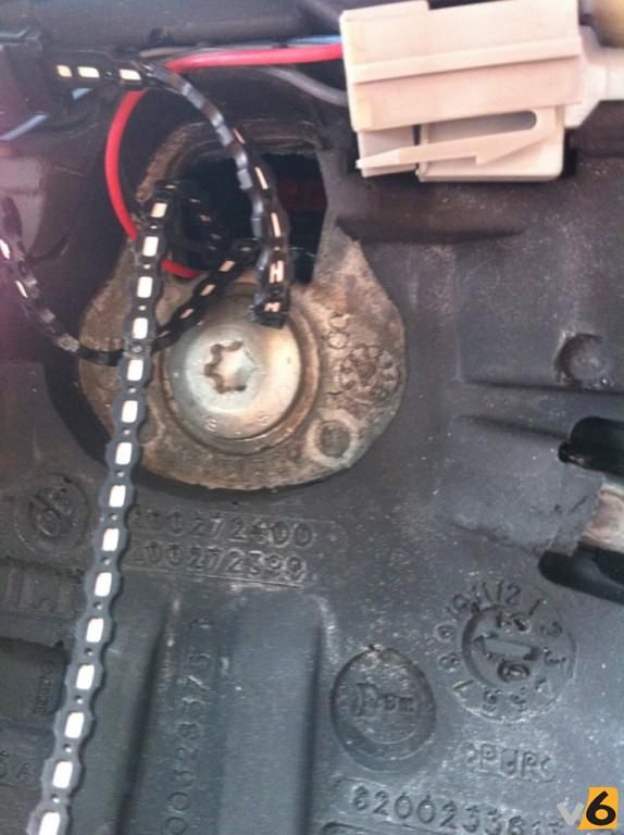
6. Right, time to get that pesky wheel off....it's held on by just one bolt. This one...surprisingly...
[img]http://i188.photobucket.com/albums/z183 ... 6225ba.jpg[/img]
For this, you'll need your ratchet, an extension bar to clear the wheel recess and a Torx/Star Size 50 bit.
[img]http://i188.photobucket.com/albums/z183 ... 16469d.jpg[/img]
Undo the bolt, but not all the way!!! You'll need to hold the wheel rim to stop the wheel trying to rotate. Leave the bolt with a few threads remaining engaged...like so :
[img]http://i188.photobucket.com/albums/z183 ... 400b50.jpg[/img]
7. Now go all Hulk Hogan on the wheel. Give it a few taps towards you with your hand around the circumference, wobble it side to side, pull on it, use the Force, whatever, until the wheel pops off and pulls forward until it is stopped by the bolt...you did leave the bolt in slightly didn't you?? As you will now realise, without leaving the bolt in, when the wheel released suddenly you would probably have ripped off all the wires from the column too. Good trick eh?
8. Go ahead and undo the bolt completely, keep it somewhere safe! You'll be left with this...
[img]http://i188.photobucket.com/albums/z183 ... 5136d2.jpg[/img]
So, pull the wheel towards you off the spline and feed all the wires carefully out through the hole in the back of the wheel.
9. Now comes the first tricky part. As you may notice, the cruise control connectors are different on the 197 wheel vs. the standard wheel. There's many ways to do this, I was adamant that I didn't want to cut any of the car's loom, so that's the method shown here.
First up, snip off the connector from the old wheel. Cut it so you leave about 1cm of the wires sticking out of it. This'll leave you with a wheel looking like this...
[img]http://i188.photobucket.com/albums/z183 ... ae4d04.jpg[/img]
You can now throw it in the bin, the best place for it
10. OK, now snip the cruise control connector off your 197 wheel. Snip the wires as close to the connector as you can. You can throw this little connector away, it's not needed again.
11. Now remove the pins from the original connector. These photos show the pins already removed, sorry about that! To remove the pins, pop off the yellow cap as below (pull wings out sideways and then lift it up)...
[img]http://i188.photobucket.com/albums/z183 ... 9b0e59.jpg[/img]
Now lift the little plastic tabs one at a time, carefully, you don't want to snap them. As they are raised (red arrows), pull the pins out one by one in the direction of the blue arrows. You should have that cm of wire sticking out the end to pull on.
[img]http://i188.photobucket.com/albums/z183 ... 88eb5e.jpg[/img]
13. OK, soldering time!!! First get prepared.
Let's start with the 2 connector pins you just removed.
- You'll have two wires about 1cm long each coming out of the pin
- Strip as much insulation as you can off of the two wires
- Now twist all the exposed copper strands together
- Use some solder to "tin" the copper strands.
- Repeat this procedure for both pins.
Now, the steering wheel wires.
- You have 2 cut grey wires and 2 cut yellowy-green wires
- Strip about 8mm of insulation off all the wires
- Find the 2 grey wires and twist all their copper strands together. Now tin the merged wires with some solder
- Find the 2 yellowy-green wires. Again, twist all their copper strands together and tin with some solder
- Cut 2 lengths of heatshrink. About 2 cm should do it. Slide one over the combined grey wires and push it up and out of the way for now. Slide the other wrap over the combined yellowy-green wires.
Right, you're prepared. now you need to solder a pin onto each set of wires. Try and make the soldered joint as streamlined and neat as possible!! So, one pin onto the grey wires and one pin onto the yellowy-green wires. Here's mine, mid progress...
[img]http://i188.photobucket.com/albums/z183 ... 3818d7.jpg[/img]
Once you're happy the solder is good, pull the heatshrink down the wires and over the joint. Heat with a heat-gun to create a nice neat joint. Here are mine...
[img]http://i188.photobucket.com/albums/z183 ... f7999e.jpg[/img]
14. Now, let's get the connector block back on. First thing first, look on the end of the connector....
[img]http://i188.photobucket.com/albums/z183 ... 4132be.jpg[/img]
See that "1" and "2" ???? The grey wires' pin needs to go into the "1" position, and the yellowy-green wires' pin needs to go into the "2" position!!!
The pins will only go in the "right way up" as the hole is rectangular. It's just a cast of push the pins in the same way they were removed. No need to lift the tabs this time, they'll click in and lock the pins in place, like so...
[img]http://i188.photobucket.com/albums/z183 ... a58cf4.jpg[/img]
Now just snap on the yellow cover...
[img]http://i188.photobucket.com/albums/z183 ... 933980.jpg[/img]
15. RIght, that's the electronicery out of the way, onto the mechanical headache....
So, if you hold the original wheel up against the 197 wheel, you'll notice the spline is longer on the 197 wheel and the rear of the wheel is a different side profile too. If you just bolt the 197 wheel on without any modification it rubs on the plastic column cowlings, adding friction to the steering, sounding awful and stopping the wheel self-centreing.
You need to find a standard M20 metal washer and reduce the outer diameter slightly. I used a linishing machine, but you could also simply use a file to achieve the same result. Thanks to Russo for producing this drawing of exactly what you need to achieve :
[img]http://i188.photobucket.com/albums/z183 ... 0131cd.jpg[/img]
16. OK, nearly there. So thread your modified washer onto the steering spline. Now offer up the 197 steering wheel. Feed all the various wires (2 airbags, horn and cruise control) through the hole in the wheel. Make sure the horn wires are sat in their little retainer as they tend to work their way out. Line up the wheel with the spline (there is a master spline, so the wheel can only go on in one orientation). Push the wheel on slowly. Make sure that the two lugs on the steering wheel will go into the two plastic forks on the indicator self-cancelling mechanism. See below (bits to watch out for highlighted in green):
[img]http://i188.photobucket.com/albums/z183 ... 0bee68.jpg[/img]
17. Alright, we're tanking now, easy sailing from now on. Well, almost. Go ahead and bolt the wheel on. USE THREADLOCK!!!!!!! (that mistake's been made once, LINK)
[img]http://i188.photobucket.com/albums/z183 ... b9dcc8.jpg[/img]
18. Torque the bolt pretty tight, the wheel shouldn't be able to move in our out, side to side nor up and down! You should now be looking at something like this...
[img]http://i188.photobucket.com/albums/z183 ... 33c3f9.jpg[/img]
19. Go ahead and connect the horn up. Again make sure the wires are sat in their little retaining groove behind the wheel.
20. RIght, next problem. The bigger connector from the original wheel hasn't got room to sit in the new wheel. We need to open up the rubber channel down the right hand side of the wheel. Just use a stanley knife or scalpel and cut out the rubber, it's quite soft. Be careful not to stick the knife straight through the back of the wheel, this IS possible, I learnt the hard way [/b}. OK, your groove should end up something like this..
[img]http://i188.photobucket.com/albums/z183 ... 84fc82.jpg[/img]
As you can see, the connector can now fit much more "flush" than previously....
[img]http://i188.photobucket.com/albums/z183 ... 71ad7f.jpg[/img]
21. Go ahead and connect up both halves of the cruise control system. Push the connector into your new groove so it's out of the way.
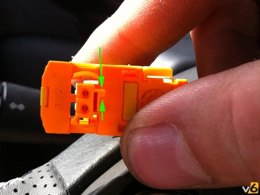
22. You'll notice you have 1 green airbag connector and 1 orange airbag connector. The green one is OK, but the orange one needs modification to fit the new airbag. The little square tab marked with arrows below needs to be removed. You can again use a craft knife or similar, the plastic is quite easy to cut.
[img]http://i188.photobucket.com/albums/z183 ... f977a7.jpg[/img]
23. Right then, on the 197 airbag you'll notice the right hand socket is green. No prizes for guessing the green connector goes in here. Go ahead and push the connector into place and then close the locking tab firmly. Keep holding the weight of the airbag so not too much strain is put on the green connector and push the modified orange connector into place on the left side of the 197 airbag (the plug on the airbag is actually marked purple).
24. You now have the wheel all connected up. Take a quick glance behind the airbag and make sure all the wires are recessed as well as possible (especially the CC wires). The airbag simply pushes into place. There's two metal tabs at the back and two plastic retaning tabs on each side at the front. Just make sure the airbag is square up to the wheel and push all over, quite firmly. You should hear (and see) everything clip into place.
25. Re-attach negative terminal to the battery. Make sure it's tight. Re-assemble the bonnet area (not forgetting the rubber weather seal!!)
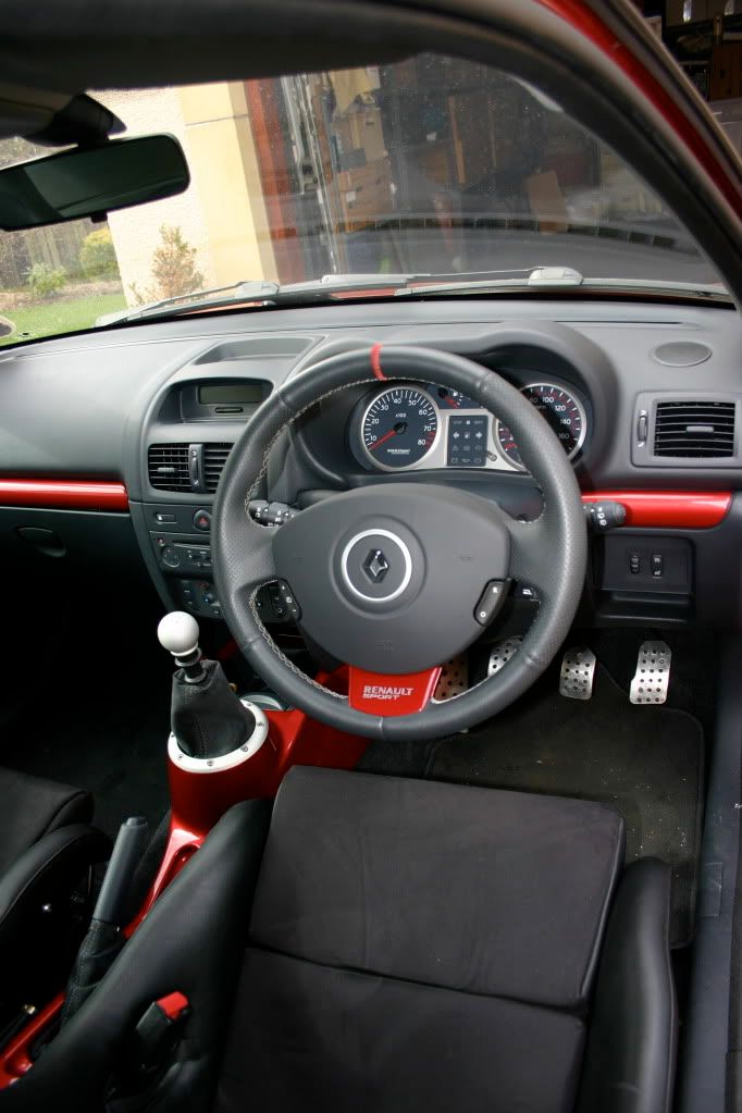
25. Ta-daaaa! You're done. Take her for a spin, check the horn works, the cruise control functions as expected and crash into a wall to check the airbag will deploy.
[img]http://i188.photobucket.com/albums/z183 ... f87712.jpg[/img]
Clio V6 -- 5 Alpine Turbo -- Clio II RS -- 4CV Grand Luxe -- 5 TR -- Clio II Ragnotti dCi "daily" -- Megané III estate dCi
-- ClioV6register.nl--
-- ClioV6register.nl--
erg bedankt adrian.
hier kan ik wel wat mee
vooral 25. Ta-daaaa! You're done. Take her for a spin, check the horn works, the cruise control functions as expected and crash into a wall to check the airbag will deploy.
hahah
hier kan ik wel wat mee
vooral 25. Ta-daaaa! You're done. Take her for a spin, check the horn works, the cruise control functions as expected and crash into a wall to check the airbag will deploy.
hahah
-
Adrian
- Berichten: 1383
- Lid geworden op: wo 25 apr 2007 11:37
- Car: Clio V6, 5 AlpineT
- Locatie: Brouwershaven
- Contacteer:
Haha dat is idd een manier 
Clio V6 -- 5 Alpine Turbo -- Clio II RS -- 4CV Grand Luxe -- 5 TR -- Clio II Ragnotti dCi "daily" -- Megané III estate dCi
-- ClioV6register.nl--
-- ClioV6register.nl--
nog even terugkomend op dit topic !
in mijn stuur zit geen cruise control ingebouwd. ( maar in mijn auto wel de aansluiting, zoals dat standaard is )
heb ik genoeg aan de cruisecontrol aansluiting van het 3rs stuur, om dit aan te kunnen sluiten?
alvast bedankt.
in mijn stuur zit geen cruise control ingebouwd. ( maar in mijn auto wel de aansluiting, zoals dat standaard is )
heb ik genoeg aan de cruisecontrol aansluiting van het 3rs stuur, om dit aan te kunnen sluiten?
alvast bedankt.